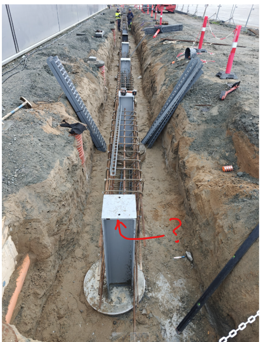
Practical engineering philosophy
A 4.5m tall wall was started to build - before design finished. Foundations looked suspicious. Calculation shows modifications are needed.


Industrial foundations, walls and roof. The “roof” was all they wanted but…
Disaster prevented. Their anchors held 16kNm - where 360kNm is required.
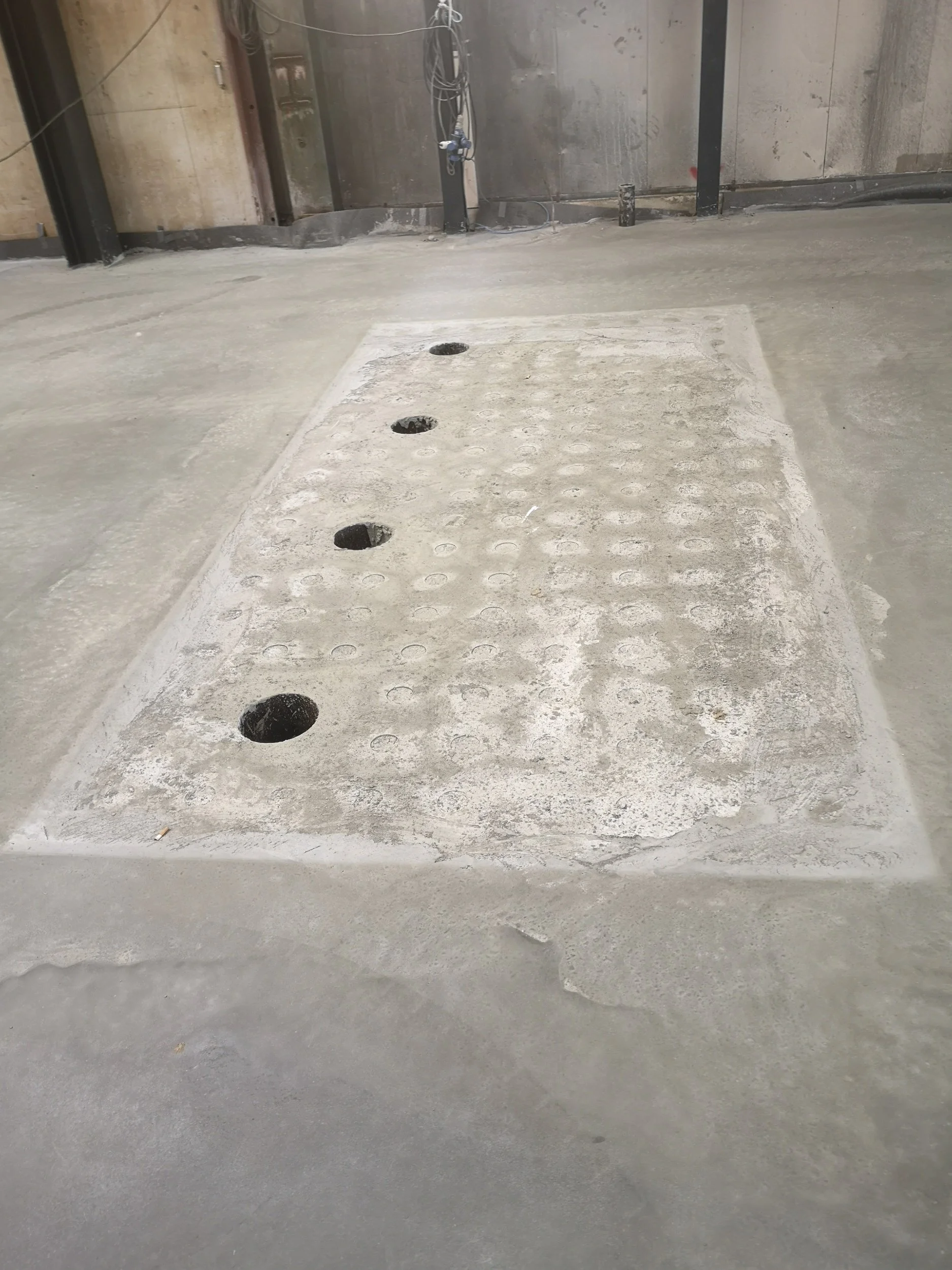
Reinforced concrete… Factory floor with custom foundations.
Disaster prevented. Floor redesigned, bridges, anchors 10x overload found….


Rail road, heavy industry - Australia.
Disaster prevented. Investor threatened to ship back multimillion EUR order back… but we fixed it.
EU Railroad spring / damper system.
Opportunity created. Solution suitable for EU market found. Cost approximation found
Concrete truck attachment.
New market unlocked. Verified and certified for Swedish market.


Rear Under Protection (RUPD) - car crash sim.
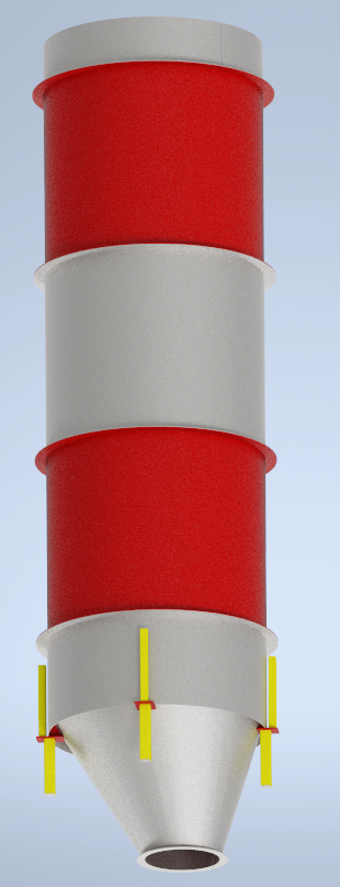
Sand holding silo, for a cement factory. From design - to manufacturing drawings… in weeks.
New product unlocked. CE mark. 20t lifting winch frame for offshore crane. Product line expanded towards a 2x stronger solution.

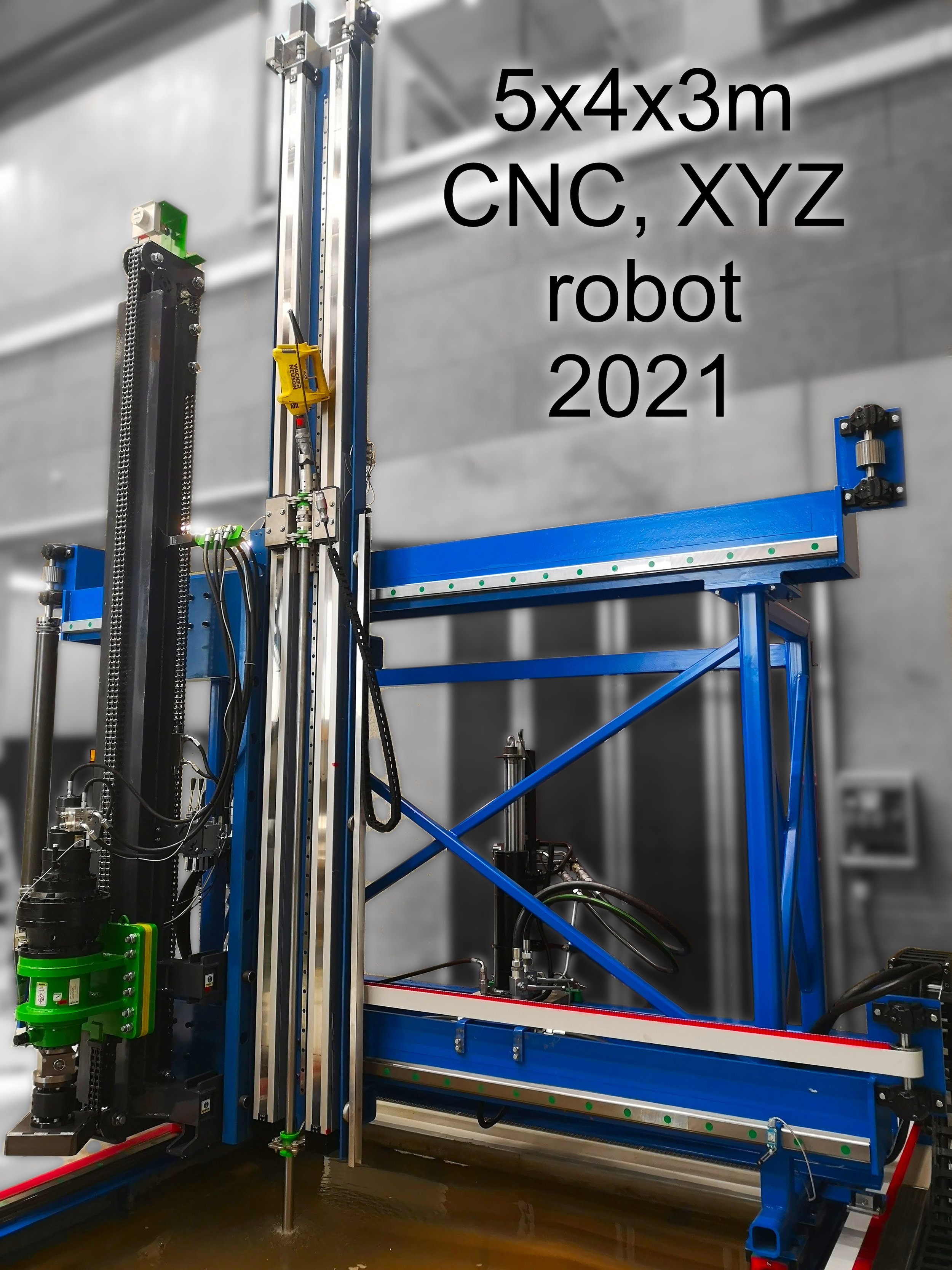
New Research capacity unlocked. And Patent. 3t heavy, 5m tall, 3×5m size CNC machine designed in 4 weeks. Built and operating flawlessly. Design of the frame and joints to hold loads. Hydraulic valve selection for custom PID controlling. Electrical and electric components. Coding of sensors (custom load cells, lidar, data logging, etc…). And a hammer (patent) to test things in-situ, outside of the laboratory. Aalborg University, BUILD. :)
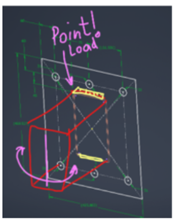
Preliminary design.
A "research grade" task... experimental reinforcement.
Calibrated for crack propagation.
Overkill, but... dynamic load safe.
500 ULS cycles... EN3 compatible.
1. Fatigue safe 2. Feels stable (not "shaky"). 3. Certifiable for CE mark.
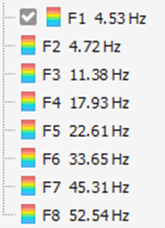
Natural frequency - below 10Hz is not good.
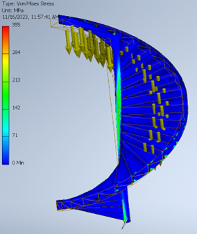
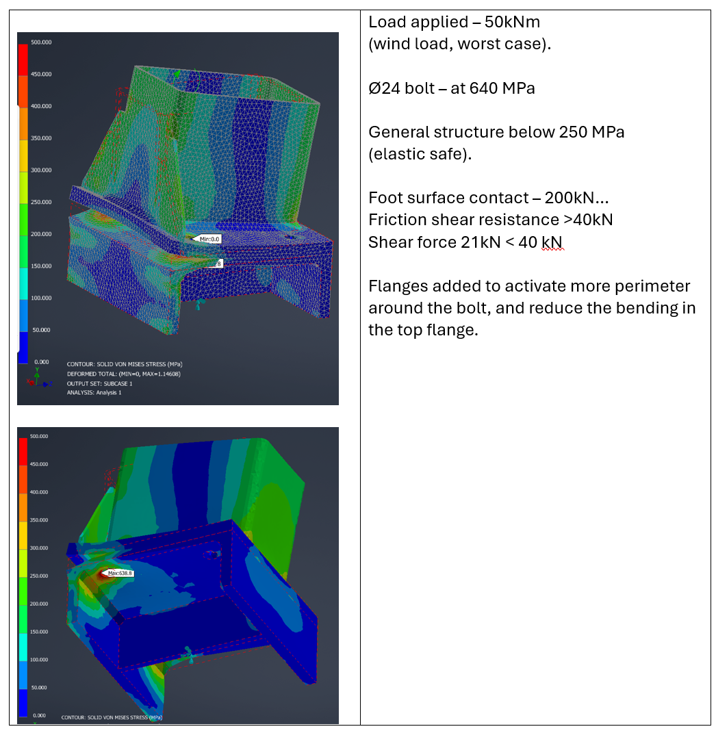
Stress in ULS case... ok
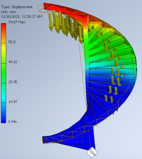
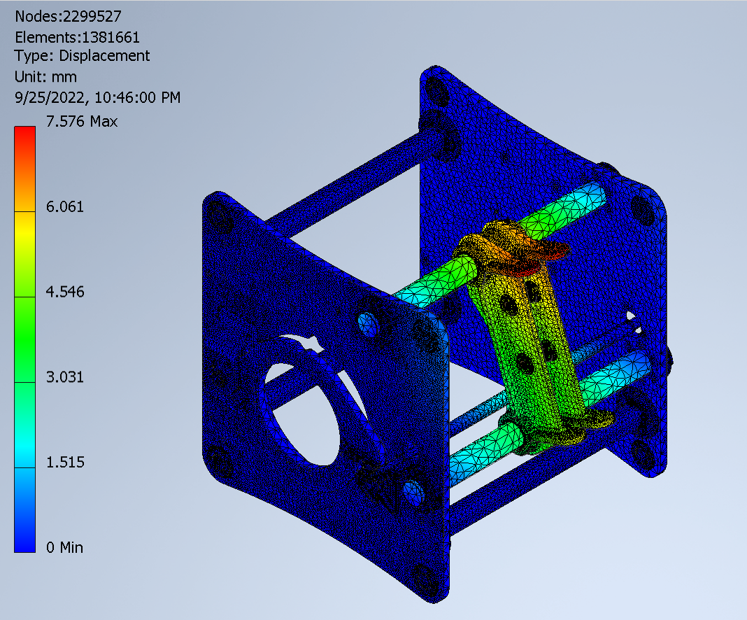
Displacements...
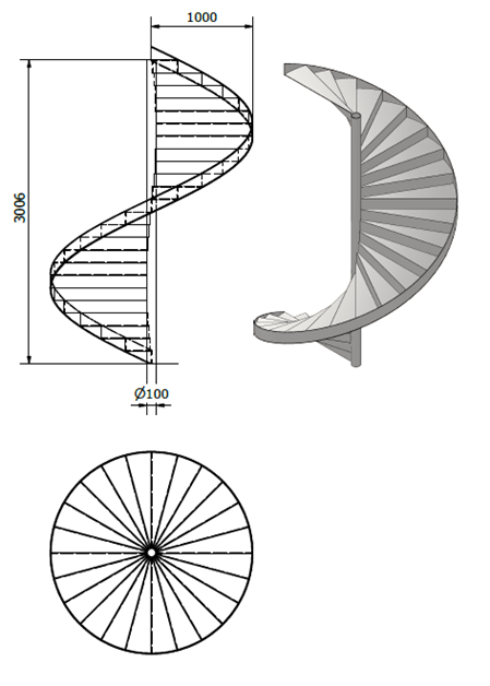
Manufacturing / production drawings generated...
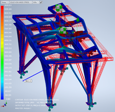
Frame dynamic response - for shaky engines, and moving parts.

The frequency response is scary bad.
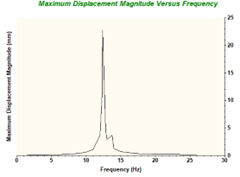
After adjusting, one frequency remains dominant, and is plausible to dampen effectively.
Thermal analysis
Thermal analysis is a BEAST…
Coupled with stress fields, fatigue, gets even harder.
Managing of tasks can benefit from “fast engineering feedback”. It often helps:


Reality is perfect, it never makes an error.
It was not made for us, it knows not we exists.
Observe the unpredicted, predict the unobserved.
Inductive and deductive - converge to truth, not false (yet).
Nothing is true. Some is not false (yet).